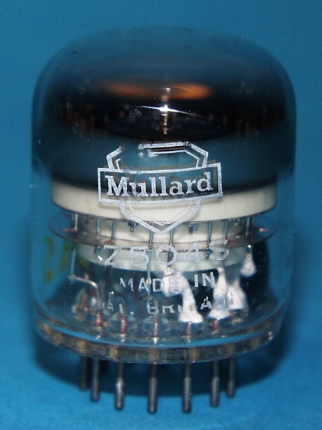
Dekatron counting tube
Bi-directional double-pulse decimal counting & selector tube.
Neon filled
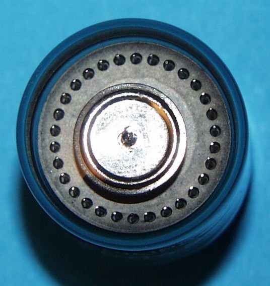
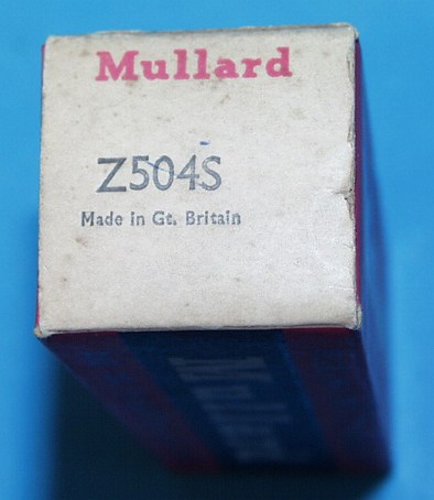
Z504S (Mullard)
Dekatron counting tube
Bi-directional
double-pulse decimal counting & selector tube.
Neon filled
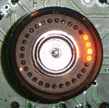
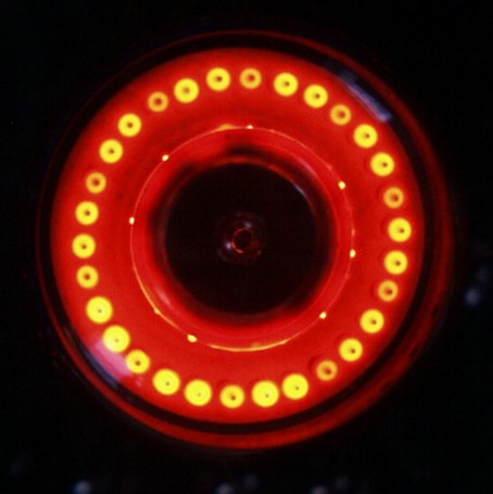
The following pictures show the tube spinning.
Of course, only one of the cathodes is glowing, but the opening time of the
camera leads to that different pictures:
a middle opening time of the camera:
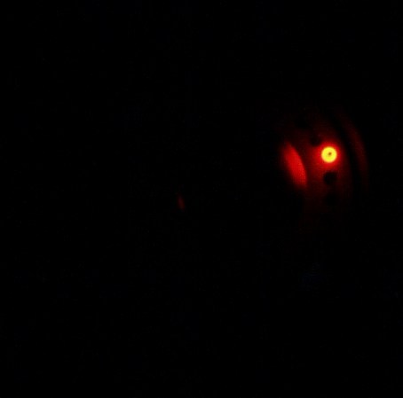
a short opening time of the camera:
a long opening time of the camera:
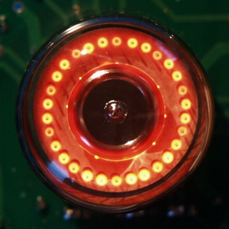
by night, with long opening time of the camera:
An animation of a spinning dekatron:

| German | English | ||
| Röhrentyp | Tube type | Z504S | |
| Hersteller | Brand | Mullard | |
| Vergleichstypen | Substitutes | ZM1070, 8433 | |
| Zähl-Richtung | Counting direction | bidirectional | |
| Arbeitsweise | Operation | double pulse | |
| Art | Sort | counting & selector tube | |
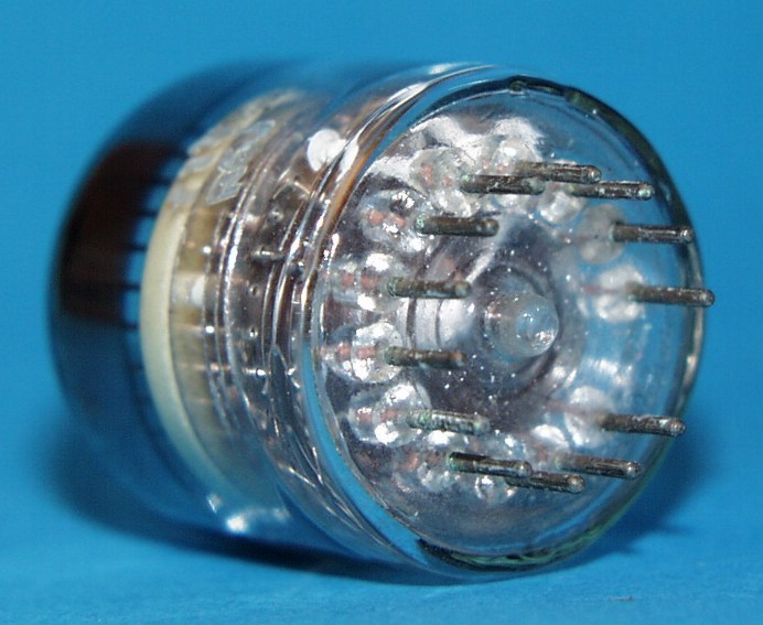
| Sockel | Base | B13B | |
| Fassung | Socket | B13B | |
| Nullposition | Zero position | Pin 7 | |
| Zähl-Schritte | Counting steps | 10 | |
| Anzahl der Hilfskathoden | Number of guides | 2 | |
| Gasfüllung | Gas filling | Neon | |
| Röhrendurchmesser maximal | Tube diameter max. | mm | 30 |
| Röhrenhöhe maximal | Tube height max. | mm | 42 |
| max. Zähl-Geschwindigkeit | Max. counting speed | kHz | 5 |
| Betriebsspannung minimal | Supply volt. min. | V | 375 |
| Betriebsspannung typisch | Supply volt. typ. | V | 475 |
| Betriebsspannung maximal | Supply volt. max. | V | 1000 |
| Brennspannung minimal | Maintaining voltage min. | V | 185 |
| Brennspannung typisch | Maintaining voltage typ. | V | 190 |
| Brennspannung maximal | Maintaining voltage max. | V | 205 |
| Anoden bzw. Kathodenstrom min. | Anode/cath. current min. | µA | 250 |
| Anoden bzw. Kathodenstrom typ. | Anode/cath. current typ. | µA | 340 |
| Anoden bzw. Kathodenstrom max. | Anode/cath. current max. | µA | 525 |
| Netzteil Leistung minimal | Power supply power min. | mW | 160 |
| Anodenwiderstand typisch | Anode resistor typical | kΩ | 820 |
| Spannungsdifferenz zw. 2 Kath. max. | Voltage between 2 cathodes max. | V | 140 |
| Transferspannung minimal | Transfer voltage min. | V | 45 |
| Transferspannung typisch | Transfer voltage typ. | V | 80 |
| Transferspannung maximal | Transfer voltage max. | V | 140 |
| Hilfskathodenvorspannnung minimal | Guide bias volt. min. | V | 25 |
| Hilfskathodenvorspannnung Impulsbetrieb typ. | Guide bias typ pulse op. | V | 40 |
| Hilfskathodenvorspannnung maximal | Guide bias volt. max. | V | 60; 140 |
| Hilfskathodenimpulsspannung (Rechteck) | Guide signal voltage rectangle | Vp | -120 |
| Hilfskathodenimpulsspannung eff. (Sinus) | Guide signal voltage eff. (sine) | Veff | 85 |
| Hilfskathodenwiderstand maximal | Guide resistor max. | kΩ | 220 |
| Kathodenpotential aktive Kath. max. | Cathode pot. cond. max. | V | 40 |
| Kathodenpotential inaktive Kath. | Cathode pot. non cond. | V | -14 |
| Kathodenwiderstand typisch | Cathode resistor typical | kΩ | 103 |
| Ausgangsstrom | Output current | µA | 340 |
| Ausgangsspannung | Output voltage | V | 35 |
| Resetimpulsspannung | Reset pulse voltage min. | V | -120 |
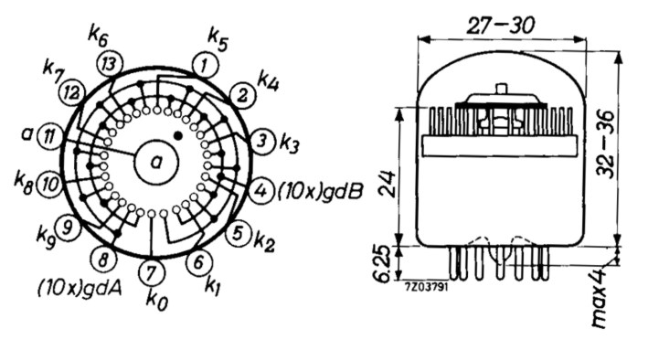
| Anschlussbelegung: | Pinout: | ||
| PIN 01 | PIN 01 | K5 | |
| PIN 02 | PIN 02 | K4 | |
| PIN 03 | PIN 03 | K3 | |
| PIN 04 | PIN 04 | G2 | |
| PIN 05 | PIN 05 | K2 | |
| PIN 06 | PIN 06 | K1 | |
| PIN 07 | PIN 07 | K0 | |
| PIN 08 | PIN 08 | G1 | |
| PIN 09 | PIN 09 | K9 | |
| PIN 10 | PIN 10 | K8 | |
| PIN 11 | PIN 11 | Anode | |
| PIN 12 | PIN 12 | K7 | |
| PIN 13 | PIN 13 | K6 |
Pinout & Outline:
Downloads/Datasheets:
Sie finden passende Datenblätter
im Datenblattarchiv.
Suchen sie dort nach dieser Type und deren Vergleichstypen.
You'll find the matching datasheets in
the datasheet archive.
Search for this type and its substitutes there.
Back
to Dieter's Nixie Tube Page
eMail to Dieter
Impressum & Datenschutz