 |
Sylvia
VFD Tube Clock
Designed by Dieter
Wächter
last update and finished:
September-07-2008
|
|
Back
to Dieter's Nixie Tube Page
Email
to Dieter
This clock-project bases on the VFD-tubes technology.
What are VFD-Tubes?
A vacuum
fluorescent display (VFD) tube is a type of tube which consists of a hot cathode
(filaments), anodes (phosphor) under a high vacuum condition in a glass
envelope.
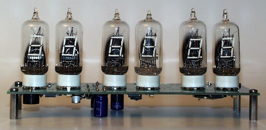
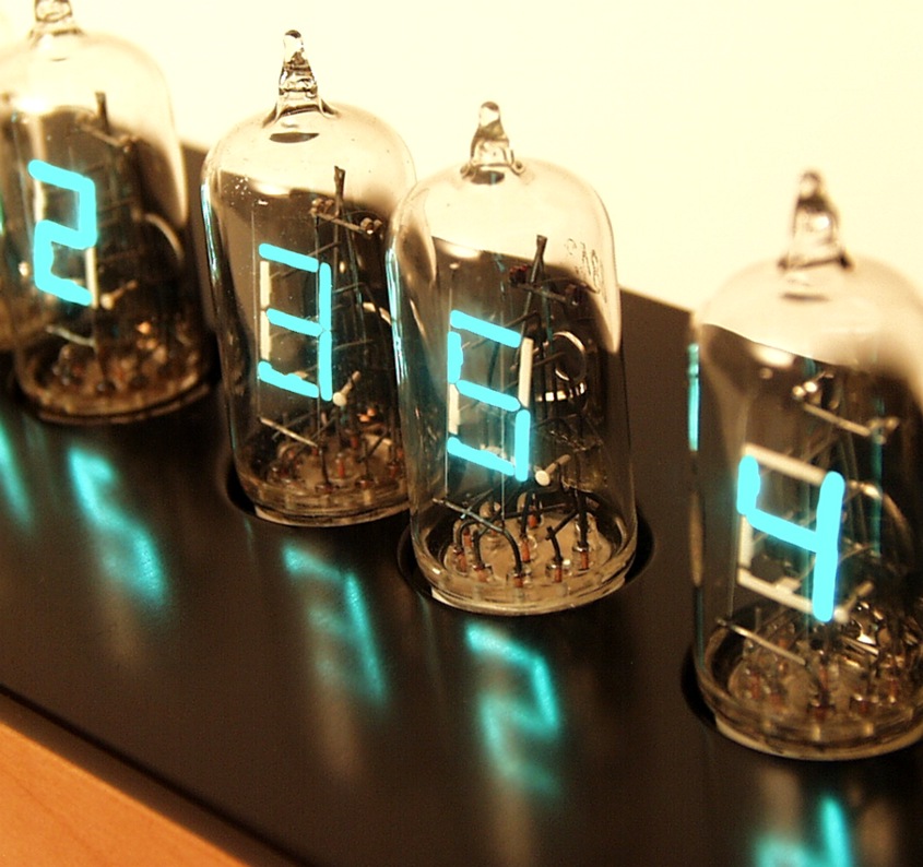
This clock uses tube types 8843 or 8894 made by Sylvania in the early seventies. The cathode is made up of fine tungsten
wires, coated by alkaline earth metal oxides, which emit electrons when heated
by an electric current. If electrons impinge on the phosphor-coated plates, they
fluoresce, emitting light to indicate the 7-segments used in this tubes.
Electrons can only reach (and "illuminate") a given plate element if the plate
is at a positive potential with respect to the cathode. They have no grid
compared to other VFD displays.
Here, at my VFD-tube page you can
find lots of pictures and descriptions of VFD tubes.
Here an example of the 8843 tubes:
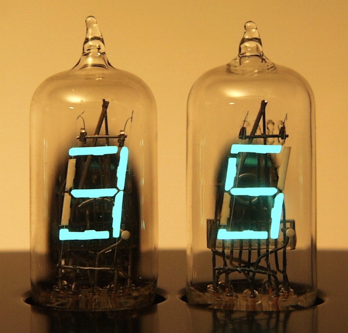 |
Step 1: Designing the
schematic
After studying the datasheets and some tests on the display I made some test
circuits and finally came to this schematic:
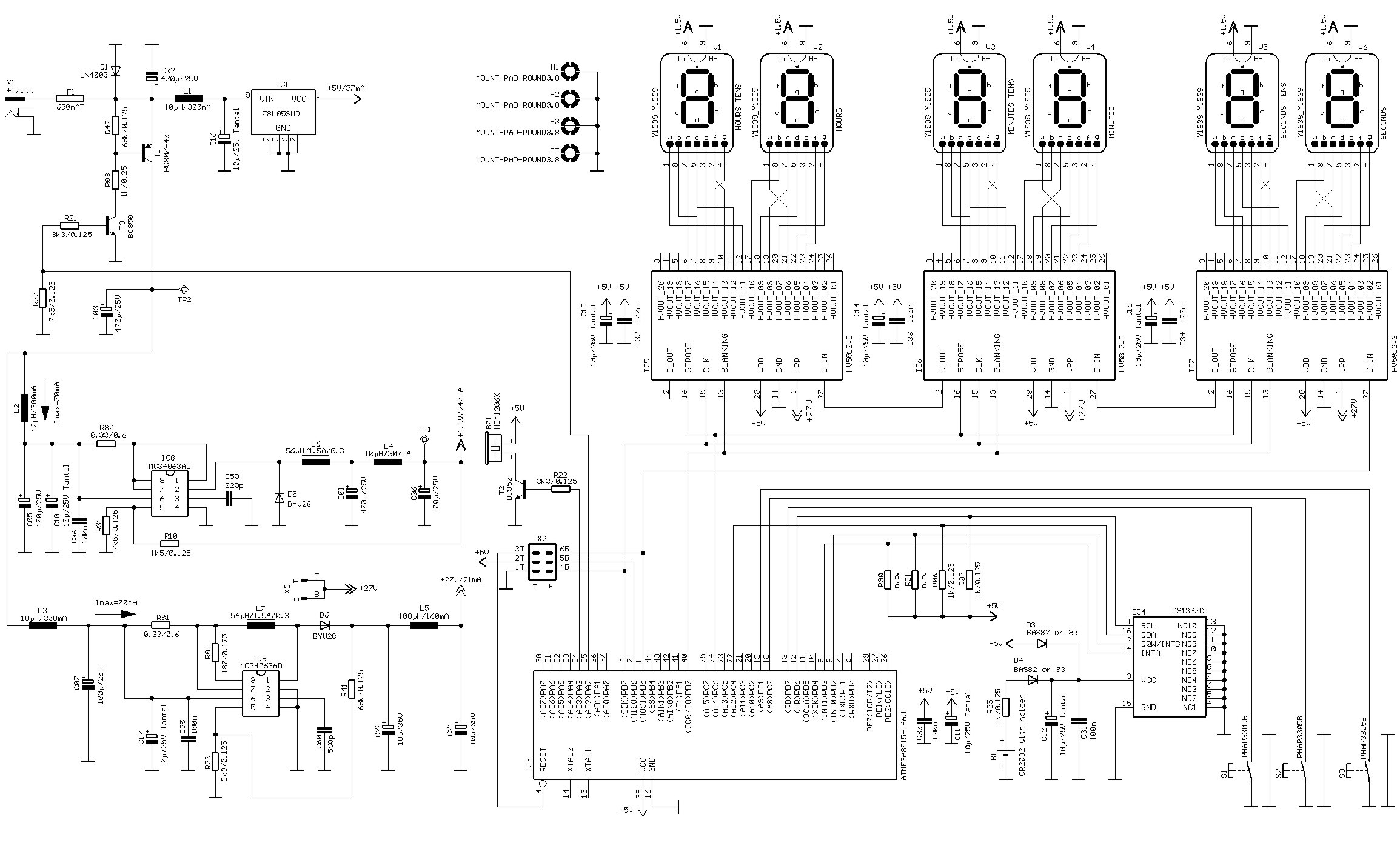 |
As you can
see a very simple design.
HV5812WG drivers, a step-down converter for the 1.5V power supply (filaments)
and a step-up converter for the 27V anode supply.
Atmega, and finally the Dallas RTC (DS1337C ) which has an on-board crystal (I like that
all-in-one chips)
I think there is nothing to explain in this schematic.
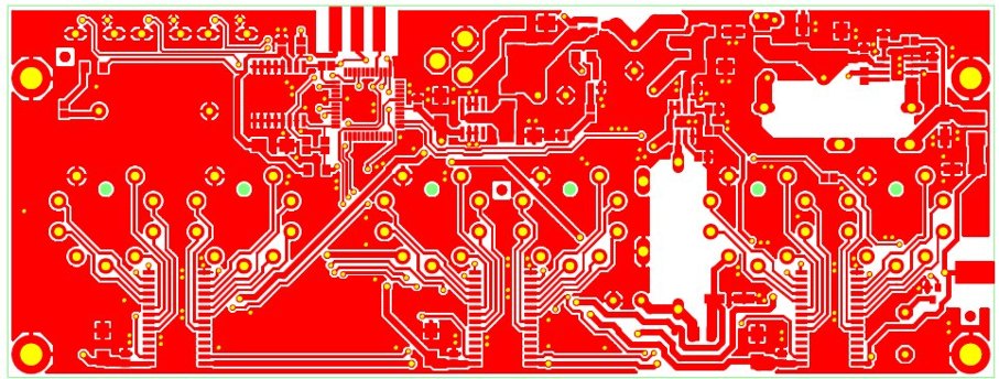
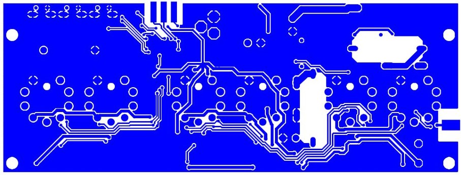
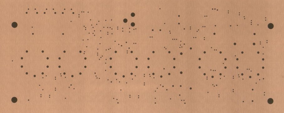
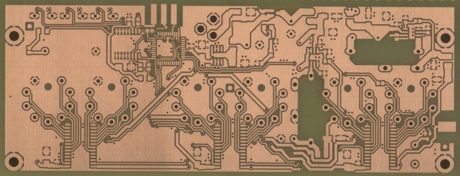
Step 2: Designing the
board
Here the production steps:
ROUTING

TOP COPPER FINISH
BOTTOM COPPER FINISH
DRILLING
MASKING
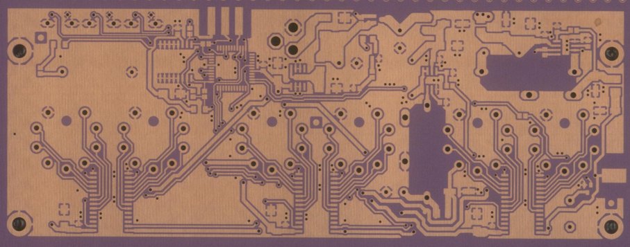
ETCHING
PRINTING
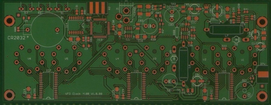
HOT AIR LEVELLING
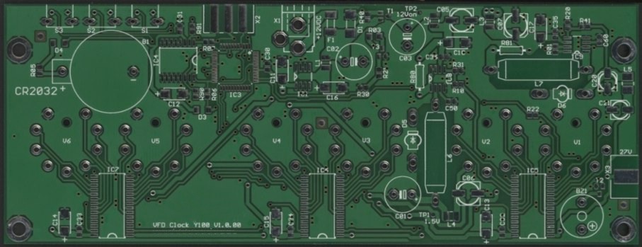

The board
measures: 180x67mm
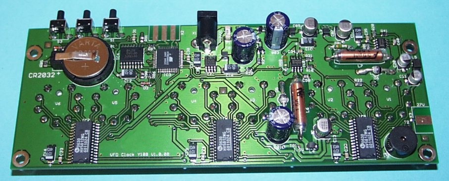
Step 3: Assembling the
board
There were no difficulties with the schematic.
Everything worked fine, although it was the first prototype.
SMD-SOLDERING
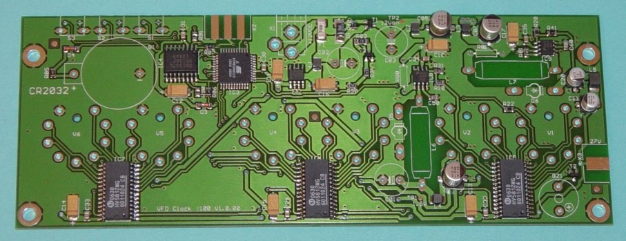
THT
SOLDERING

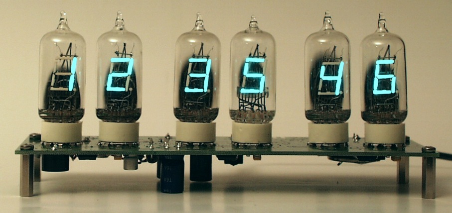
Step 4: Assembling the
board with the tubes.
TUBES OFF
FIRST
TESTRUN
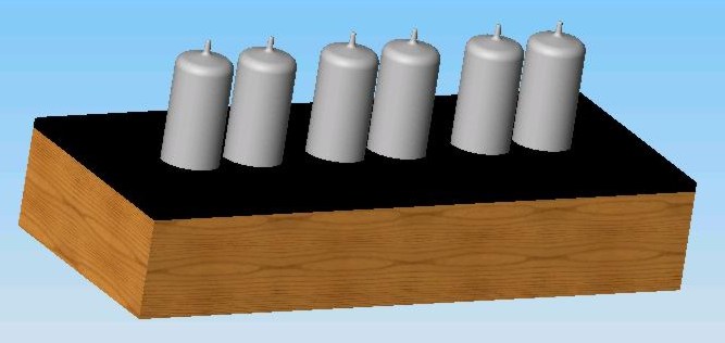
Step 5: Designing the
case
I made some designs and came to this one (3D-animation only)
It is the same as I used for my X2000 clock.
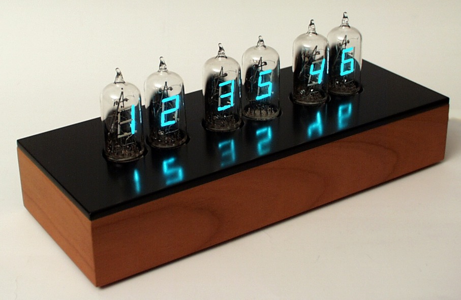
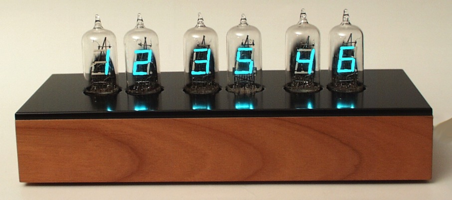
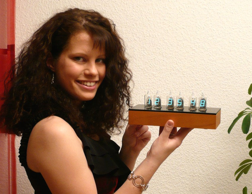
Here you see the result of the finished housing:
Step 6: The coding
The features I put in:
|
|
This
Project is finished
Thanks for reading.
Back
to Dieter's Nixie Tube Page
eMail to Dieter
Impressum & Datenschutz